So my senior design project was chosen for the David and Lorraine Freed Undergraduate Research Symposium which is in early April. As a result, I get to spend my weekend in the lab to make sure we have all the new systems up and running by then. We are starting to play around with PIR sensors and the one have has a night and daytime mode. Although I tend to like pushing things like this into software for the additional flexibility, it is pretty easy to come up with a simple circuit with the parts I had on hand.
First, a shout-out to PennApps Hardware for the photo-resistor that they gave to all the hardware hackers. I couldn't find any laying around in lab. So the photo-resistor has a resistance of ~3K when the lights are on and ~100K when they are off. So we can use this to construct a little circuit with a 2N3904 transistor.
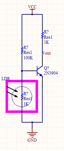
If we hook up 5V to Vcc, then we see +5 volts out when the lights are on, and roughly 0.1 volts when the lights are off. This works great as a detector, however the PIR sensor uses jumpers between pins. We want to be able to electronically control this so we need to add an additional transistor.
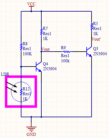
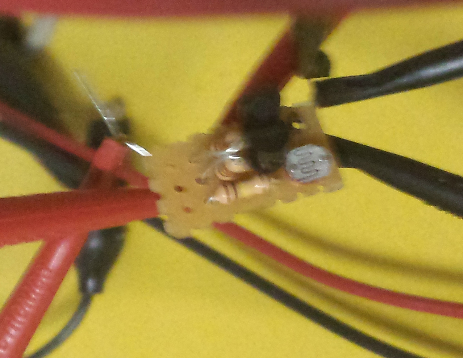
Making R9 large, ensures that we don't pull down Vout to 1 diode drop above ground. Then if it is light out, Vout will be at +5V, and Vout' will be at ground. If it is dark, Vout will be at ground and Vout' will be at +5V. Let's build it and see if it works!
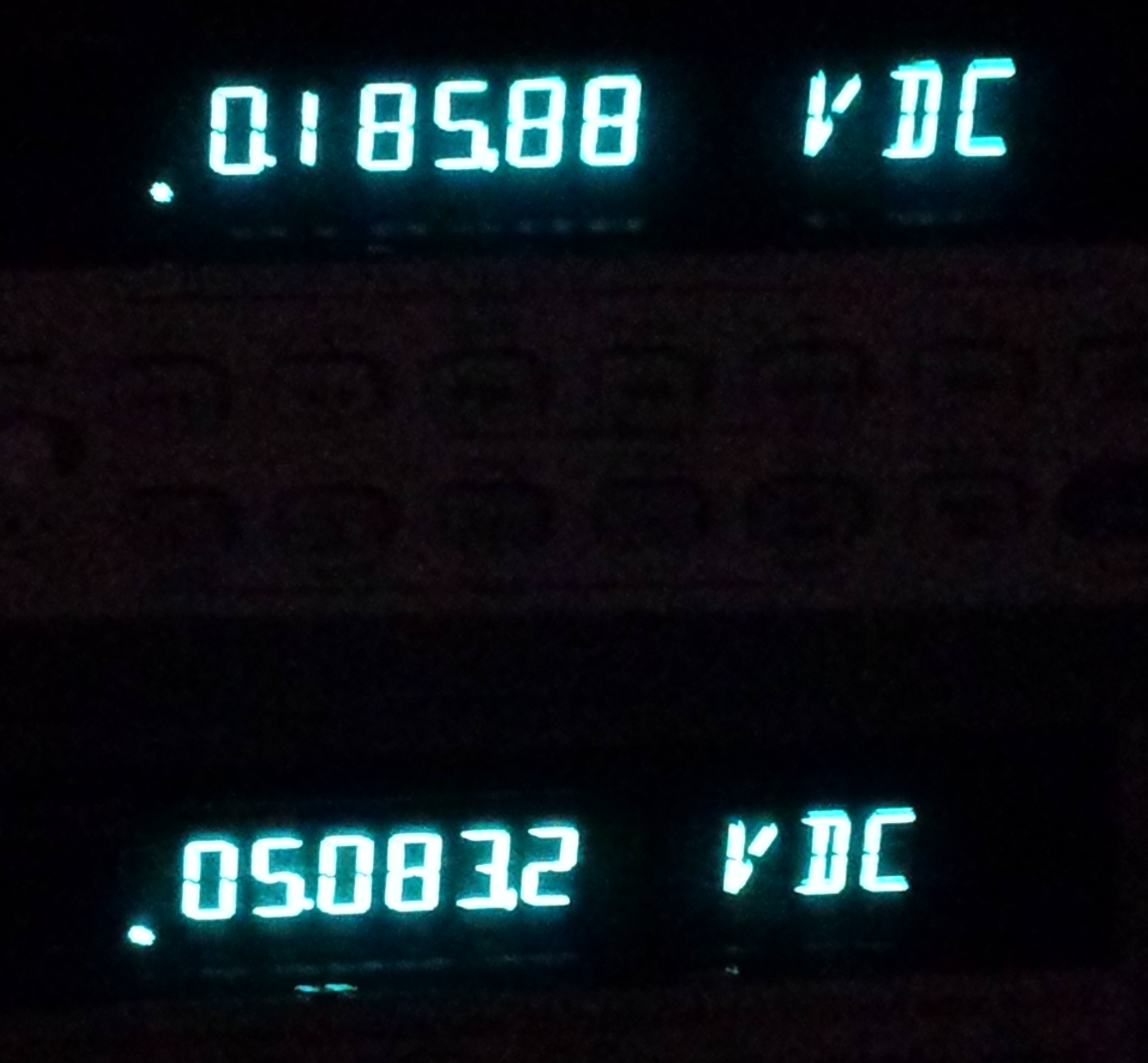
And if we hook it up to a supply we get: (Note: the top multimeter is Vout, the bottom is Vout')
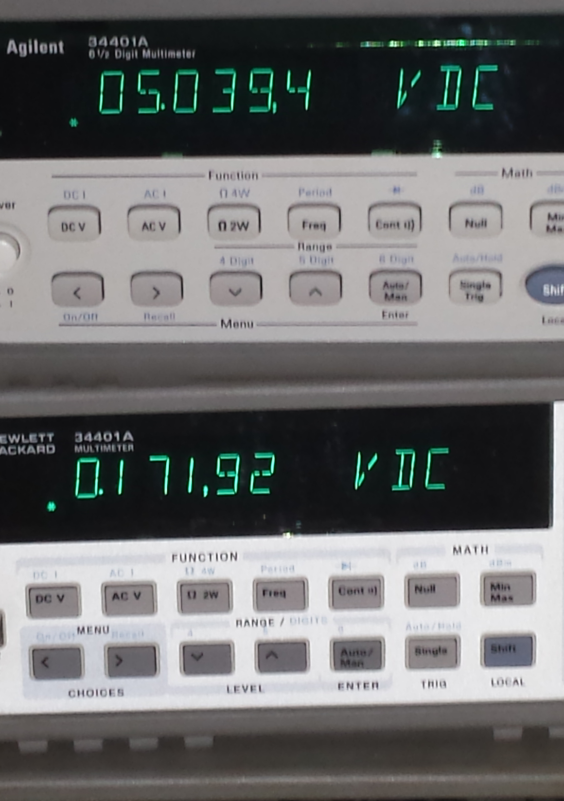
I hate to admit this, but when I first took the picture in the dark, I turned on my flash to try to make the readings from the multimeter. After realizing my stupidity, here is the result.
As for the end application, instead of running it off the +5V rail, I just have to hook Vcc up to the main pin, then this circuit will short it down to the correct daytime / nighttime pin.